Welcome to part two of our custom cooling assemblies discussion…
In part one, we covered the most common arrangements used for cooling semiconductor devices: standard heat sinks and fan assemblies, heat pipes, vapor chambers and liquid coolers. In this section we look at the mechanics of actually connecting a bespoke cooling solution to the CPU and motherboard without damaging any of the components. We will assume that for the sake of discussion that the device is a single CPU as these are the most common item that requires heat removal in an embedded system but the theory is relevant to any semiconductor device that generates heat. Additionally there maybe a number of devices that requires heat removal, so immediately any cooling solution becomes more complex and costly.
In this two part article we will…
- Custom Cooling Assemblies Explained: Part one: Discuss the various methods available to cool electronic devices. (this article)
- Custom Cooling Assemblies Explained: Part two: Consider aspects of the mechanical design and manufacturing process.
Mechanics
Whichever methodology is chosen for cooling semiconductor devices, the connection between the device and the bespoke hardware needs to be designed correctly. Each semiconductor manufacturer should have mechanical mounting requirements for each of their specific devices and datasheets need to be consulted in order to understand the recommended connection methods, else damage may occur to the device, printed circuit board or cooling assembly.
The cooling method chosen must make a good thermal and mechanical bond to the device to ensure that heat can be removed from the device and that the device is not damaged due to environmental problems such as noise or shock. Figure 3 shows an example stack up with a LGA2011-0 footprint device which is made up of heat sink, Independent Loading Mechanism (ILM), CPU, socket, motherboard and back plate.
Figure 3 – LGA2011-0 Socket Stack (image courtesy of Intel)
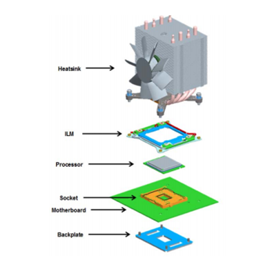
In designing a cooling assembly the maximum package loading specification of the device must be taken into account which should not be exceeded during assembly, shipping or standard use. Specifically the CPU surface and socket should not be used as a load bearing surface as it will damage the device or the solder connections to motherboard. Additionally the heat sink must have uniform compression over its surface to ensure good heat transfer.
Typically a back plate is used to give mechanical rigidity to the motherboard around the area of the CPU and helps to minimise board bow and twist. Without this the motherboard is likely to be damaged as there will be little mechanical support under the CPU, which in turn will likely lead to damage around any localized solder connections on the PCB.
The IPC specification on PCB design state that the maximum bow and twist for surface mount boards is 0.75%.
Commercial cooling units typically use captive screws or push pins in order to ensure a good attachment between the cooling assembly, CPU and motherboard to ensure that the pressure between the various parts is controlled.
Manufacture
The system needs to be designed with manufacture in mind to ensure repeatable builds can be achieved. Full ESD precautions need to be taken when handling any printed circuit board or semiconductor device such as a CPU to ensure damage does not occur to electrical devices. Anti-static wrist straps, bench mats and flooring should be used to minimise the potential damage to electronics when being handled. Latent ESD damage may occur whereby a device is partially damaged but continues to perform its intended function until at a later stage intermittent or permanent failures occur which will lead to failures in the field.
While assembling the entire system, extreme care needs to be given to the build process. Appropriate manufacturing jigs and fixtures maybe required which will allow production operators to physically hold the printed circuit board and the cooling assembly while also trying to permanently connect the parts with tooling. Without appropriate manufacturing jigs and fixtures there is a strong possibility that any slippage of tools or parts will damage the PCB or CPU.
Conclusions
Any bespoke cooling solution needs careful thought and there is no one ‘ideal’ solution that can be recommended, as each system requirements will differ.
What initially may be thought of as a relatively simple mechanical sub-assembly has the potential to turn into a long term issue if incorrectly understood and implemented. Printed circuit boards and CPUs are relatively fragile devices and if the cooling system is poorly designed or manufactured potentially costly problems may occur. Equipment failures may not be seen immediately but will appear over time especially if changes to the equipment are made such as software upgrades or operational use case changes. These may cause units that were previously functionally working to be pushed over their reduced operating threshold. Additionally latent ESD damage caused in manufacture could occur at any time.
Failures in the field are not only costly to repair as a stock of replacement units will be required and the manpower to replace them, but they may be located in inhospitable or inaccessible places where high reliability is essential. Additionally frequent breakdowns can lead to a loss of confidence in the product and reputation to the suppliers business.