On occasion, BVM’s customers have to design bespoke cooling assemblies due to the environment that their end product is required to operate in. This may be because the enclosure that holds the electronics has to be sealed from ingress or the equipment is subject to high stresses from external factors. While using lower power CPUs such as the Intel Atom or an ARM device can reduce the issue of heat removal, the customer may ultimately require higher computing power and therefore a more powerful CPU is required. If a commercial rather than embedded CPU is required then heat becomes a serious issue as the top end of Intel’s current CPU line up dissipate around 150 Watts, while AMD are topping a massive 250 Watts.
In this two part article we will…
- Custom Cooling Assemblies Explained: Part one: Discuss the various methods available to cool electronic devices. (this article)
- Custom Cooling Assemblies Explained: Part two: Consider aspects of the mechanical design and manufacturing process.
The main aim of the cooling assembly is to transfer the heat generated by the CPU and other semiconductor devices to ensure overheating and potentially fatal damage does not occur. Traditionally this consisted of a large Aluminium heat sink and Fan assembly which is mounted on the top of the main CPU, sandwiched together with special paste to ensure a good thermal bond. The heat is then transferred from the CPU via the heat sink and fan to the air within the enclosure. The enclosure is typically vented with forced cooling fans to ensure cool air is drawn into the enclosure and the warm air is pushed out into the surrounding atmosphere. Heat pipes are often used to enhance the performance of traditional heat sinks and in laptops where heat has to be moved to a different physical area of the enclosure. For high performance and gaming PCs, liquid cooling units are often used which pump a liquid around a sealed assembly in order to transfer the heat to a radiator and fan assembly mounted on the exterior of the enclosure.
Cooling and Industrial systems
As an added issue in industrial systems there is often the requirement to seal the product in order to meet certain Ingress Protection (IP) ratings for intrusion and moisture protection. This in turn restricts the options for keeping not only the CPU cool, but all other electronic devices within the assembly. Additionally the equipment maybe required to withstand high shock environments when used on vehicles, trains or aircraft which also negate the use of ‘off-the shelf’ cooling components.
When designing a custom cooling assembly for your application, firstly obtain the Thermal and Mechanical Specification and Design Guide for your CPU. This will detail specifics for the family of devices that you have chosen. Each CPU may have a different footprint from what you have used before and will therefore require a different mechanical mounting methodology which is usually advised by the manufacturer.
Heatsinks
The cooling assembly must be able to remove the maximum power from the device at a maximum ambient temperature without heating the ambient atmosphere. The image below shows the heat transfer path for a traditional heat sink assembly.
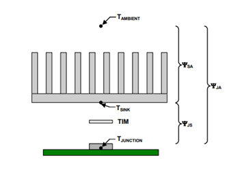
As an example, if your device has a TDP of 10W, a maximum junction temperature of 100°C and your maximum ambient temperature is 55°C, then ΨJA = 4.5°C/W. In order to calculate heat sink size, check the manufacturer’s parameter ΨJS for the chosen device and this will allow you to calculate the maximum heat sink thermal resistance. On commercial systems fans are normally mounted on the heat sink to help move the heat to the local atmosphere and will therefore increase the efficiency of the system.
If the enclosure is sealed as is often the case in industrial designs then the localized ambient atmosphere will rise as the heat transfers from heat sink to the local atmosphere. Eventually the ambient temperature will reach a point at which the heat sink can no longer dissipate enough heat from the CPU and the device will either shut down or become thermally damaged. Therefore this type of design is not recommended for completely enclosed systems.
Heat Pipes and Vapor Chambers
An alternative to the traditional heat sink for removing heat is the use of a heat pipe. Heat pipes are normally a sealed copper pipe which contain a liquid and uses evaporative cooling to transfer the heat generated by the CPU to a heat sink. The advantage of this method when used in an enclosed design is that the heat sink can be designed as part of the equipment enclosure and thus the heat gets transferred to the outside world via a heat pipe.
This method works by transferring the heat generated at the CPU into the liquid within the heat pipe. As the temperature rises, the liquid vaporizes and travels up the length of the pipe until it cools and condenses back into a liquid. The cooled liquid then returns to the hot end of the pipe through capillary or gravity where the cycle is repeated. Therefore the heat is moved away from the CPU to the other end of the tube which is normally connected to a heat sink assembly. The inside of the heat pipe typically has a copper powder, mesh or grooves attached to the inside wall which forms a capillary wicking structure through which the liquid can move once the vapor condenses back to a liquid.
Heat pipes offer a solution in which sealed units can move heat generated by the CPU to another physical position and are a potential solution for enclosed designs.
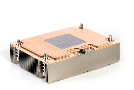
Vapor chambers use a similar concept to heat pipes but instead use the entire body to cool the CPU. This means that a lot of heat can be transferred through a small design and so presents a solution to height sensitive applications such as laptops. This still poses a potential issue in an enclosed design whereby the heat from the CPU will be held in a sealed enclosure. The image below shows the bottom of a commercial vapor chamber.
As a general rule, heat pipes are used to move heat and vapor chambers to spread heat. In a situation where the heat has to be moved to an external point such as the outside of the enclosure a heat pipe would normally be the preferred solution as the pipe(s) can be shaped to meet a custom design.
Liquid coolers
Liquid coolers function by cycling a liquid (often water) via tubes from the top of the CPU to a radiator and fan assembly in a similar way to an engine cooling system. A liquid cooler incorporates a water block that incorporates a heat conductive metal which is attached to the CPU. The top of the water block has a liquid passed through it which transfers the heat from the CPU to the liquid and pipes attached through which the cooling liquid is pumped to a radiator and fan assembly in order to transfer the heat into the atmosphere. A reservoir is normally required to hold extra liquid to allow for air bubbles to be replaced as the system circulates.
Liquid coolers are not usually recommended for industrial systems due to the need of regular maintenance and potential damage to electronic components from the liquid as the system degrades or becomes damaged due to the operating environment. Liquid cooled systems also tend to be expensive compared to other solutions.